This page is intended as a how-to guide for replacing the speedometer drive assembly on 91-92 Toyota MR2s. 93 and later MR2s have an electronic speed sender that differs from the one shown here. This page contains:
Speedometer/Odometer failure is a common problem on high mileage 91-92 MR2s and is often due to a failure of either the gear insert or the "key" between the right-angle adapter and the cruise control sender. Fixing either of these pieces require removing the sub assembly from the transaxle.
Before you attempt to remove the sub-assembly, be certain that is where the problem lies. The mechanical cable running between the sub-assembly and the gauge cluster is made of two segments. These segments are joined underneath the car on the driver's side. By removing the plastic shields at about the mid-point of the car, you can get access to where these two cables are joined. Separate them and grip the protruding pin with the chuck of an electric drill. If you spin the drill, you should see the speedometer move. If not, the problem lies in the gauge cluster or the forward cable. If the speedometer does move, the problem lies in the rear cable or the sub-assembly. NOTE: try spinning the drill both ways when doing this test. It will only work one way, and unfortunately I don't remember if it's clockwise or counter-clockwise. UPDATE: Multiple people have e-mailed me to confirm that the cable must be spun counter-clockwise. Thanks!
There's one other check you can do if you have cruise control. The cruise control speed sensor is between the sub-assembly and the rear speedo cable. If the rear speedo cable is the problem, your cruise control will still work. If the cruise control doesn't work, you'll need to remove the sub-assembly. Bear in mind there's a minimum speed (35?) for the cruise control to work.
Lastly, here's two cheat-sheets you can use to determine your speed in gears from the tachometer while you wait to get your speedo fixed. I rounded the #'s to the nearest 250 RPM, since that's what the tic divisions on our tachs are. Thanks to Net2DaHoop from the MR2OC.com boards for pointing me to the NA ratios, originally I just had numbers for the Turbo transmission. This should be accurate enough to keep you out of trouble, but no guarantees. The raw data for these tables was taken from here.
| Speed (mph) | 3rd | 4th | 5th |
|---|---|---|---|
| 35 | 2750 | 2000 | 1500 |
| 40 | 3250 | 2250 | 1750 |
| 45 | 3750 | 2500 | 2000 |
| 50 | 4000 | 2750 | 2250 |
| 55 | 4500 | 3250 | 2500 |
| 60 | 4750 | 3500 | 2750 |
| 65 | 5250 | 3750 | 3000 |
| 70 | 5750 | 4000 | 3250 |
| 75 | 6000 | 4250 | 3500 |
| Speed (mph) | 3rd | 4th | 5th |
|---|---|---|---|
| 35 | 2750 | 2250 | 1750 |
| 40 | 3250 | 2500 | 2000 |
| 45 | 3750 | 2750 | 2250 |
| 50 | 4000 | 3250 | 2500 |
| 55 | 4500 | 3500 | 2750 |
| 60 | 4750 | 3750 | 3000 |
| 65 | 5250 | 4000 | 3250 |
| 70 | 5750 | 4500 | 3500 |
| 75 | 6000 | 4750 | 3750 |
This should be a relatively straightforward job, do-able in an afternoon. It took me much longer, partly because I didn't order all the parts in advance, and partly because I didn't go about it the best way. My motivation in writing this guide is to make sure this job goes smoothly for anyone else who tries it. Overall the job isn't hard, but it does involve working in tight spaces with typically stubborn bolts.
This guide covers removal of the sub-assembly without removing the stock exhaust. I STRONGLY recommend removing the stock exhaust before attempting this fix. It will make it much easier, as the stock exhaust prevents easy access to many of the parts you need to get to. Live and learn. If you have an aftermarket exhaust, you may not have this problem. Required tools:
Step 1: Start by raising the rear of the car using your wheel ramps or jack stands. If using jack stands, place them far enough to the sides of the cross-member that they won't block your wrench handle when you remove the 3 cross-member bolts. It's a good idea to soak all the bolts beforehand with PB blaster or brake cleaner to loosen them up. If you can spray them and let them soak overnight, even better.
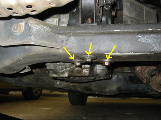
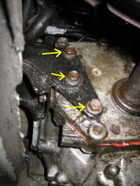
Step 2: Remove the three 14mm bolts holding the rear motor mount to the cross-member. The three bolts are shown below by the yellow arrows.
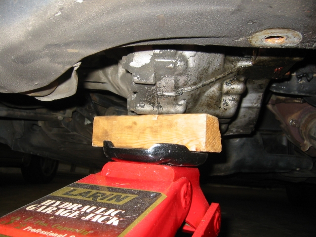
Step 3: Place your floor jack under the transaxle and jack it up slightly. It's a good idea to use a block of wood to avoid marring the transaxle housing. This takes some of the load off the rear motor mount, which we will be removing. Even though the other motor mounts will support the motor just fine, it's probably a good idea to leave the floor jack supporting the transaxle for the rest of the job. You may have to reposition it slightly later on to get at some of the bolts.
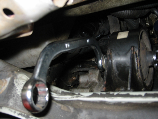
Step 4: Remove the through-bolt shown below using a 17mm wrench. Just use a single wrench on the driver's side, the passenger side nut is welded to the motor mount bracket. It helps if you jack the transaxle up enough so that the rear motor mount is no longer touching the cross-member, as this removes the load from the through-bolt. This step was extremely difficult in my case because the bolt was somewhat rusted on, and because I didn't have enough clearance to get any torque on it. This is one area where removing the stock exhaust first will pay big dividends. After multiple PB blaster soakings, I was finally able to break this bolt loose using a 17mm wrench and a straight piece of exhaust pipe as a cheater bar. I didn't have enough room to use a socket wrench between the cross-member and the exhaust. A narrow angle gear wrench (one that needs 10 degrees or less) might work well here. Once I broke the bolt free, I removed it using a 12 point obstruction wrench. I had to re-set the wrench after every 1/12th of a turn, so this was a very slow process.
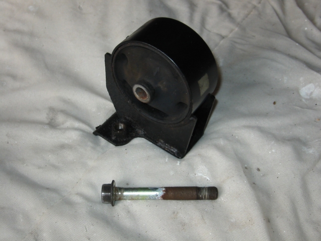
Step 5: With the through-bolt removed, remove the rear motor mount and put it aside. Here's what it looks like:
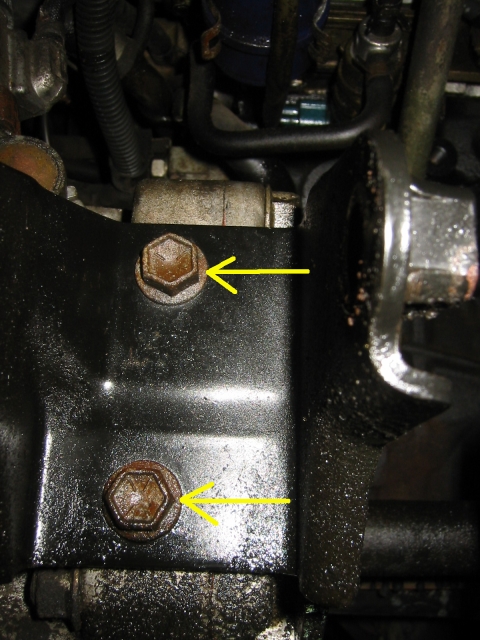
Step 6: Now we need to remove some of the motor mount bracket bolts. First, remove the three side bolts shown below with a 14mm wrench. These bolts are on the passenger side of the motor mount bracket and are fairly easy to get to, compared to the other bolts in this project.
Step 7: Next, remove the two bolts shown below with a 14mm socket. These bolts are on the "U" part of the motor mount bracket and attach to the back of the transaxle. It's easiest to get at them with a socket 6" extension and a wobble head attachment. You have to kind of snake the extension over the cross-member.
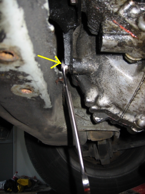
Step 8: Now for the last bracket bolt. Note we will NOT be removing this bolt, just loosening it enough to rotate the motor mount bracket out of the way. If you did remove this bolt, I have no idea how you'd get it back in without dropping the cross-member. This bolt is on the lower driver's side rear of the transaxle. The bolt is shown below, there's just enough room between the back of the transaxle and the cross-member to squeeze in with an angled-head wrench.
UPDATE: redna from MR2OC.com has informed me that it's possible to get to this bolt from above the cross-memeber if you jack up the transmission a bit more. This will allow you to remove the mount completely if need be.
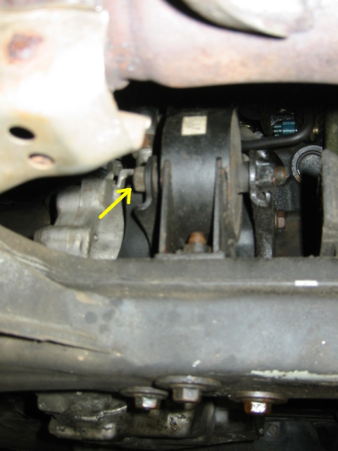
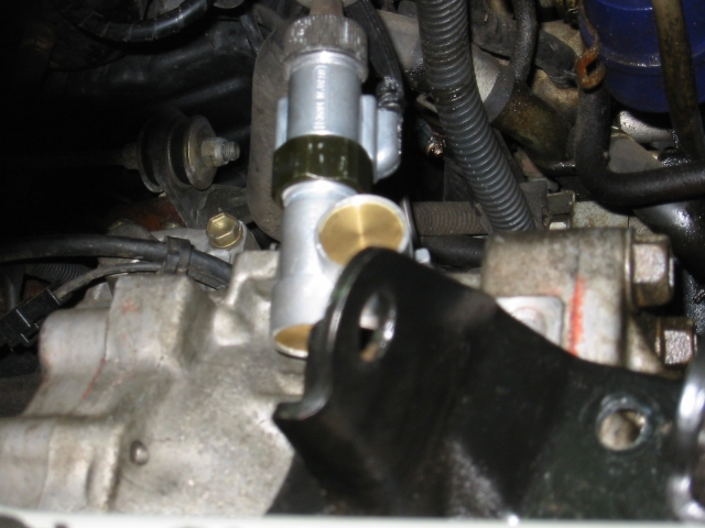
Step 9: Now we can rotate the motor mount bracket out of the way. It may have already rotated itself if you loosened the bolt in step 8 enough. If not, just grab the top of the motor mount bracket and try to swing it to the passenger side. Refer to the picture below, the bolt marked with the arrow is the one we need to get at for the next step. This single bolt attaches the speedometer sub-assembly to the transaxle.
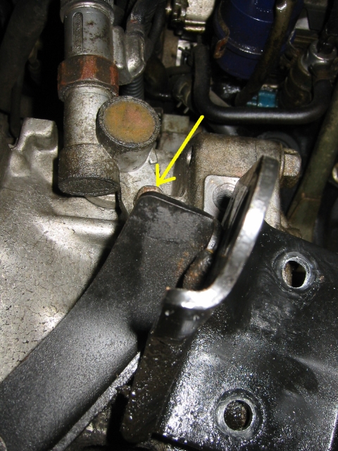
Step 10: Using a 12mm socket and extension, remove the bolt shown above. I had to seat the socket by feeling around with my hand, since the motor mount bracket blocked my view of it.
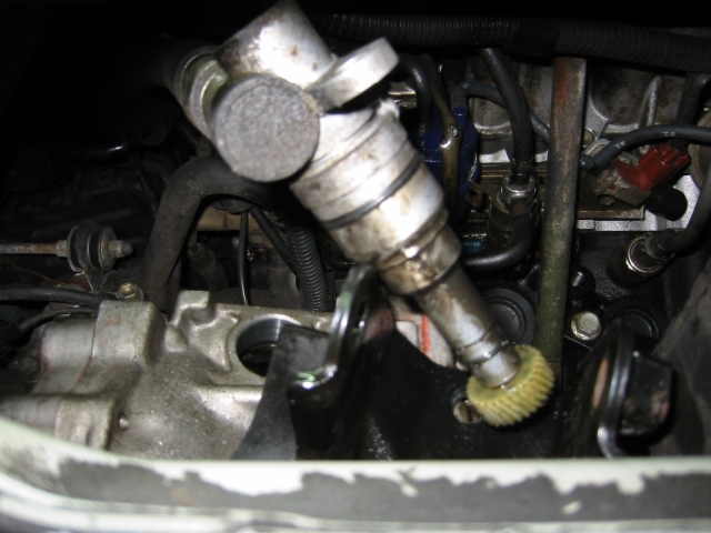
Step 11: With the bolt in step 10 removed, the sub-assembly can now be pulled out of the back of the transaxle. Get your hand up there and pull straight back on the assembly and it should pull out. It may help to twist it clockwise and counter-clockwise as you pull. Once it's out of the transaxle and you can see the plastic gear, just let it hang from the speedometer cable and go to step 12.
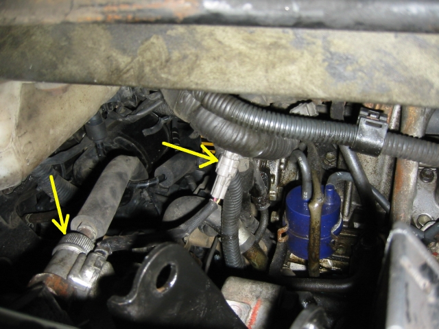
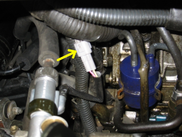
Step 12: To get the sub-assembly out of the car, there's two more things we have to disconnect. The two connectors in question are shown in the photo below. I recommend disconnecting the speed sensor wire first. My reasoning is that it's better to hang the weight of the sub-assembly from the fairly stout speedo cable, rather than the speed sensor wires.
First is the gray plastic 3-wire connector that connects the cruise control speed sensor with the main wiring harness. This is a standard toyota connector with one of those little tabs that must be depressed while pulling apart. This was extremely tricky for me to get to from the rear of the cross-member. I reached up with a long, narrow-tipped flat head screw driver and tried to press in on the little tab. I yanked and pulled on it for a while to no avail. Then I said, no joke, "Please god, let this [expletive] connector come free" and it came right off. I was stunned. I'm Episcopal, if it helps. :) Actually, now that I look at some of the photos, it may be easier to get at it from the front of the cross-member. It may also help to push down on the wiring harness from above to get it more within reach.
The second thing we need to do is to loosen the large knurled nut that attaches the sub-assembly to the speedo cable. This is somewhat easier. I used a small pair of slip-joint pliers to grab the nut, then twisted on the sub-assembly to unscrew it. A pair of channel lock pliers would work here as well. The cable is tensioned, so I found it easier to hold the nut still with the pliers and turn the sub-assembly, rather than hold the sub-assembly still and turn the nut with the pliers. YMMV. Once you've removed the nut, the sub-assembly will drop free and you can move it to a workbench for the next phase.
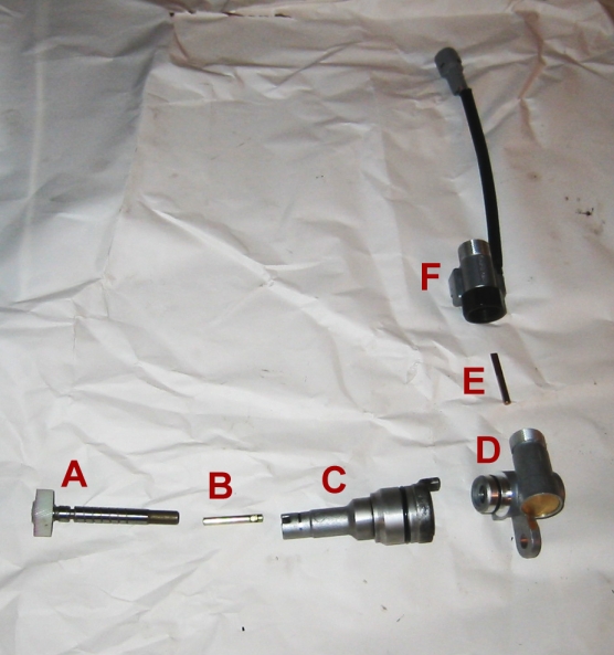
This section covers the repair of the speedometer sub-assembly. I recommend doing this phase somewhere other than the garage, preferably somewhere with good lighting so you don't lose any of the small parts. The disassembled sub-assembly is shown below.
The official names, part numbers, and prices are as follows:
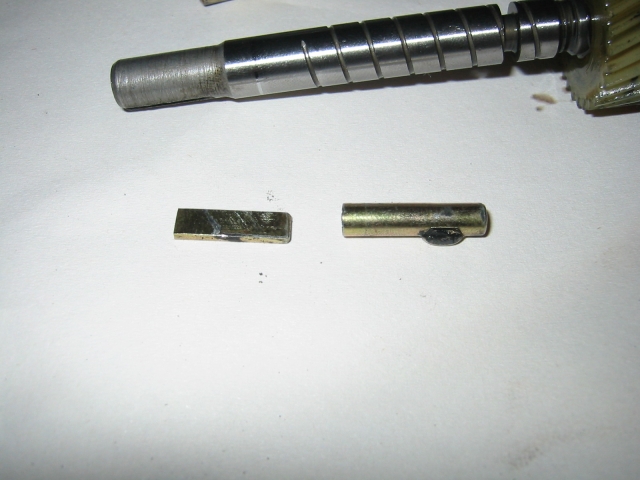
Step 13: To take it apart, first remove the G-shaped clip that holds "A" into "C." Slide "A" out and "B" should fall out with it. Next pull "C" and "D" apart, twisting as you pull will make it easier. Use a crescent wrench or channel locks to loosen the nut that attaches "F" to "D." Some PB blaster or brake cleaner may be helpful here. Don't use the tab on "D" as a gripping point, the assembly is apparently made of pot metal and is very weak. I sheared it off doing this. Once "D" and "F" are separated, key "E" should simply fall out.
Step 14: Now that it's all apart, it's time to see what's broken. Some of the most common failure modes are the little ears on "B" shearing off, a crack in the key end of part "A," or, as in my case, key "E" simply shearing in half. That's right, all this labor just to replace a 50 cent part. A picture of my sheared "E" key appears below. For want of a nail.... Anyway, I had bought parts "A" & "B" in advance from the dealer, and much to my chagrin, I had to wait a few days for a new "E". It looked like the sheared pin had somewhat mangled the faces of "D" and "F", so I ordered replacements for those parts as well. I would tend to err on the side of caution, and essentially replace the whole assembly. Parts "D" and "F" are kind of pricey, though, so if your so inclined you can just replace "A" "B" and "E", the most common failure points. "A" will come with a new G-clip and O-ring, be sure to use them. One annoying aspect of this job is that you can't tell which parts you need until you have it all taken apart...at which point your car is undrivable due to the missing rear motor mount. You can wait to get everything apart and only order the parts you need, but you may be in for a wait. Alternately, you could order everything and test out your dealer's return policy on 10 year-old parts. Good luck. Or you can just replace everything and chalk it up to preventive maintenance. I went with the later option.
Step 15: Now that we've replaced whatever was broken, it's time to put the sub-assembly back together. Simply follow step 13 above in reverse. When it's all together, check the function by turning gear "A". You should see the notch in the top of "F" turning as you do this. If not, something's still broken and you need to get it straightened out before moving on to the next phase. You don't want to go through this twice just because you forgot one of the keys.
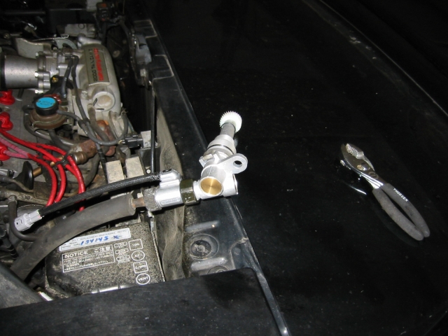
Step 16: Reconnect the sub-assembly to the speedometer cable. This is tricky to do near the transaxle, since there's an ear on the cable end that must be lined up with the notch on the top of the speed sensor. I found it much easier to pull the speedo cable up out of the engine bay from above and attach the sub-assembly there.
Step 17: Now lower the sub-assembly back down near the transaxle. It should drop down pretty easily, but you may have to finesse one of the ignition wires out of the way. Get back under the car and guide the assembly gear end back into the transaxle. It helps to twist back and forth as you push it forward. Don't insert the 12mm bolt just yet.
Step 18: Reconnect the speed sensor wire to the wiring harness. For me, connecting went a lot easier than disconnecting, not sure why. The connector is keyed so it can only go in one way, make sure you have it lined up right before you start trying to push it together.
Step 19: Check that the speed sensor and speedo cable connections are good by tugging on them lightly. Next, insert and tighten the 12mm bolt that clamps the sub-assembly to the transaxle. This was a "blind start" for me, I found the easiest way was as follows: Take the 12mm bolt in one hand and by feel insert it into the hole on the sub-assembly. Odds are it's not exactly lined up with the corresponding threaded hole on the transaxle. Twist the sub-assembly back and forth as you press in on the bolt, you should feel it slip into place one you get it lined up. Now hand-tighten the bolt to get it started, then use the socket wrench extension & wobble tip to tighten it, as in step 10 above.
Step 20: Re-install the motor mount bracket. Insert and hand-tighten the three 14mm side bolts from step 6. Do not tighten them all the way yet, leave yourself some play so you can still rotate the bracket slightly. Now insert the two 14mm bracket bolts from step 7. You may have to finesse the bracket some to get them started. Once all five bolts in this step are started, fully tighten them all.
Step 21: Tighten the "swivel" bolt that you loosened (but did not remove!) in step 8. The bracket is now re-installed.
Step 22: Put the motor mount into position on top of the cross-member then insert and hand-tighten the through-bolt. Use the floor jack to keep the transaxle jacked up slightly, so that there's a gap between the bottom of the motor mount and the cross-member. Insert and hand-tighten the 3 bolts that attach the motor mount to the cross-member (the ones removed in step 2)

Step 23: Fully tighten the through-bolt with the obstruction wrench. Lower the jack and allow the motor mount to rest on the cross-member, and fully tighten the 3 cross-member bolts.
Step 24: That's it, you're done! Congrats! Give everything a once over to make sure nothing's missing, check for left over pieces, clean up your tools, then take the car down off the ramps/jackstands and go for a spin. Hopefully you now have a working speedometer.
 Up to the top